Interacting with the Rover using Simulink
our other blogs
CanEduDev Rover: Progress Report on System Integration and Architecture
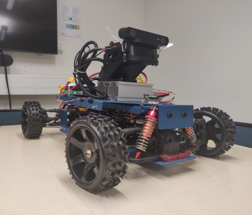
CanEduDev Rover: Technical Progress Update on System Integration We are excited to share a detailed update on the ongoing development of the CanEduDev Rover, a key project within our collaboration wi...
read moreHow LiU Formula Student Is Using the CanEduDev Rover to Drive Autonomous Innovation
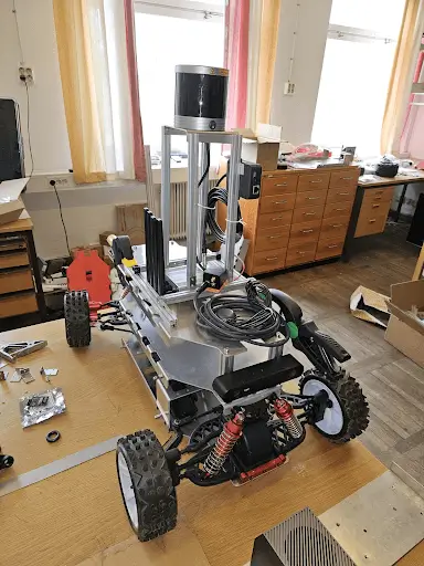
At Linköping University, the Formula Student Driverless Team has taken on the challenge of building an advanced autonomous vehicle platform. To accelerate their development and testing processes, the...
read moreUnlocking the Future with CanEduDev Rover and ROS2 Integration
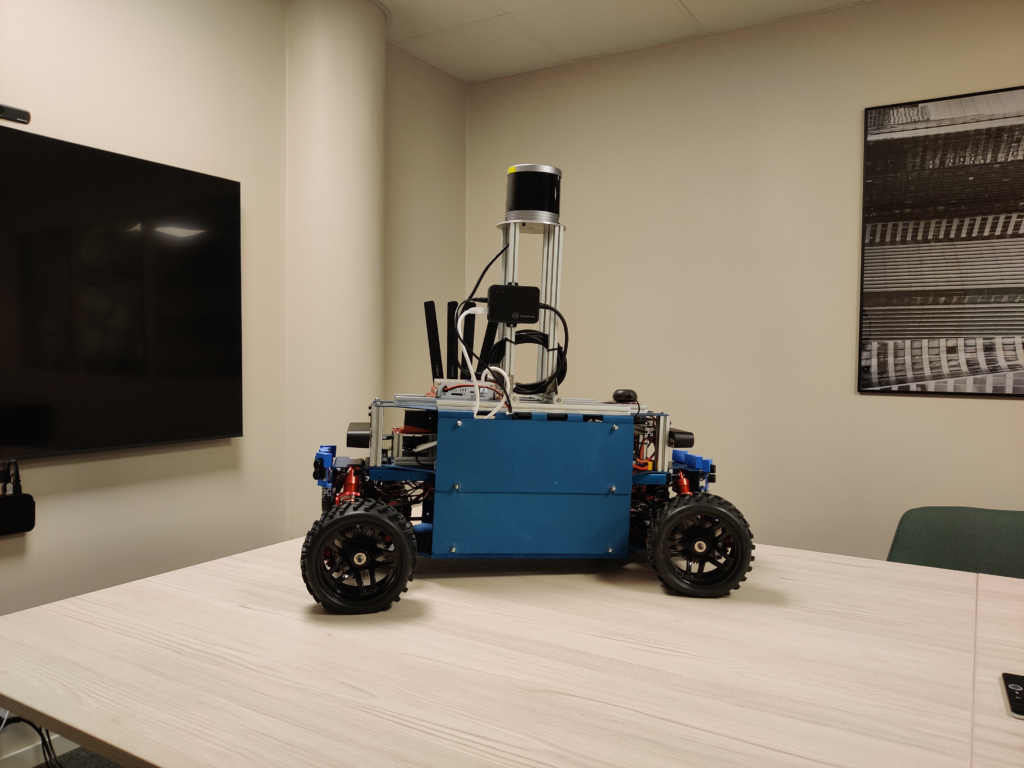
In an era where rapid advancements in automation and robotics are reshaping industries, real-time data acquisition, flexible control, and robust integration have become critical. To meet these demand...
read moreCanEduDev formally partners with Kvaser
As a newly appointed Technical Associate to Kvaser, CanEduDev is set to bring its Rover platform to the forefront of CAN technology demonstrations and education. This collaboration underscores our sh...
read moreBringing Autonomy to Life: Autoware Integration with the CanEduDev Rover
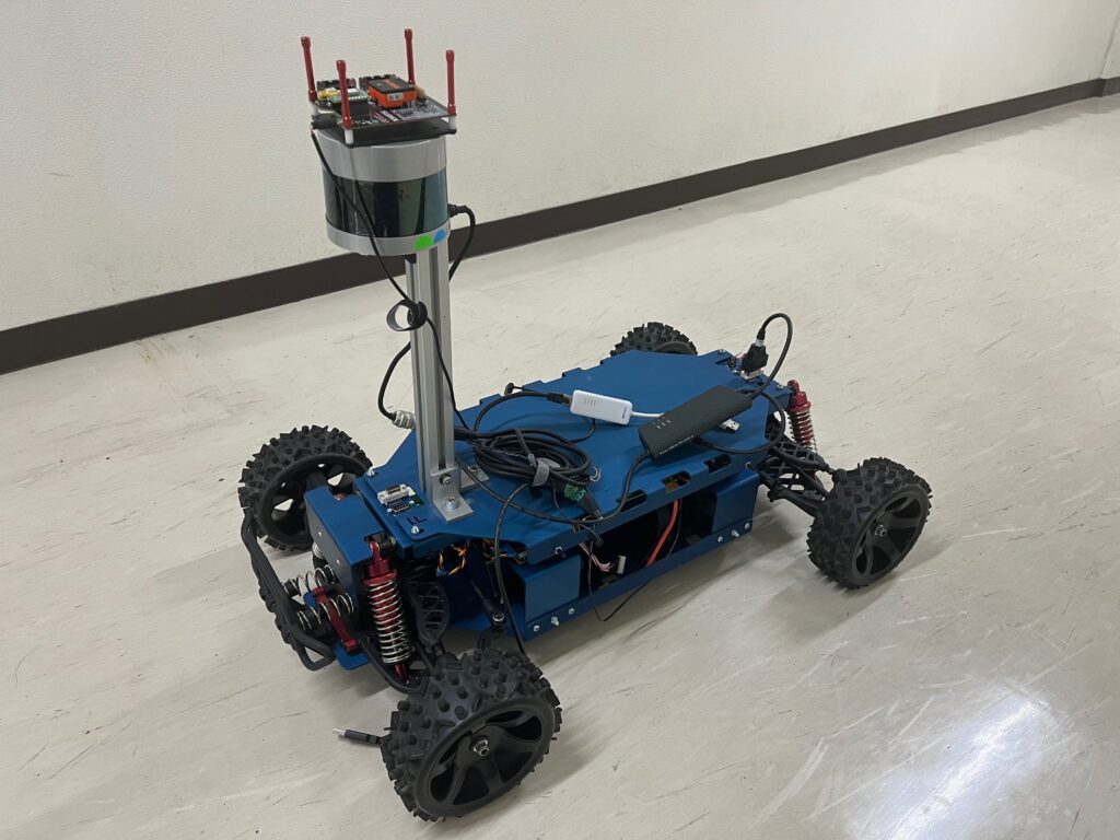
In Alex Carballo’s lab at Gifu University, cutting-edge research and hands-on robotics come together to create innovative solutions. In their latest project, headed by Tomoki Kuno, they showcase th...
read moreCanEduDev Partners with KTH and Telenor on Advanced Autonomous Driving Project
Project SummaryThe collaboration between CanEduDev, the Royal Institute of Technology (KTH), and Telenor represents a pioneering effort to push the boundaries of autonomous driving technology on a sma...
read more