Introduction
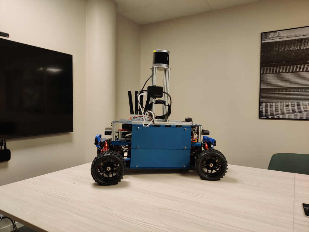
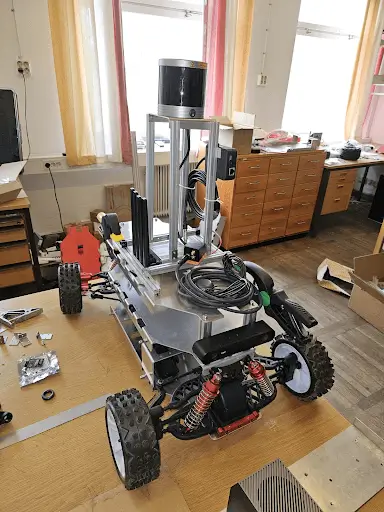
Designing a robust and efficient CAN-based control system requires careful consideration of multiple factors, including message priorities, frequency, content, and overhead. This article delves into the intricacies of CAN message design using the CanEduDev Rover as a practical case study. By understanding these elements, engineers can create more reliable and effective control systems.
CAN Basics Controller Area Network (CAN) is a high-integrity serial communication protocol widely used in automotive and industrial systems. It operates as a multi-master, message-oriented protocol, enabling various nodes to communicate without a central host computer. The differential signaling method enhances noise immunity, making CAN a preferred choice for real-time applications.
Key Components of a CAN-Based Control System
CAN Controller: Manages message transmission and reception, acting as the brain of the communication system.
CAN Transceiver: Converts digital signals from the CAN controller to the differential signals required for CAN communication.
Microcontroller: Processes data and executes control algorithms, interfacing with the CAN controller for data exchange.
Sensors and Actuators: Interface with the physical environment, providing data inputs and performing actions based on received CAN messages.
Designing CAN Messages When designing a CAN-based control system, several key factors must be considered:
Message Priorities Each CAN message has an identifier that determines its priority. Lower identifier values indicate higher priority. This mechanism ensures that critical messages, such as emergency stop signals, are processed first. For example, in the CanEduDev Rover, the message for steering control (ID 0x100) has a higher priority than the battery status messages (IDs 0x200 and above).
Frequency and Timing The frequency of CAN messages should be calibrated based on system requirements. High-frequency messages can increase bus load and cause collisions, while low-frequency messages may lead to delayed responses. For instance, the CanEduDev Rover uses different frequencies for control and status messages. The steering and throttle commands (IDs 0x100 and 0x101) are sent more frequently to ensure responsive control, while battery cell voltage updates (ID 0x200) are sent less frequently to reduce bus load.
Message Content and Payloads CAN messages can carry up to 8 bytes of data, which requires efficient payload design. The payload should include all necessary information while avoiding redundancy. Below are examples from the CanEduDev Rover:
This structure allows the system to monitor each cell’s voltage with two messages, minimizing the bus load while still providing detailed information.
Overhead Considerations Overhead in CAN systems includes the arbitration field, control field, and error-checking mechanisms like CRC. While these ensure data integrity and collision management, they also consume bandwidth. Designers must balance message size and frequency to avoid excessive bus load and ensure timely message delivery.
CanEduDev Rover Case Study
System Architecture The CanEduDev Rover features a distributed architecture with four nodes:
Steering Control Node: Converts CAN commands into PWM signals for the steering servo and reports steering position.
Motor Control Node: Manages motor speed and direction based on CAN commands.
Radio Control Node: Processes inputs from the radio control system and converts them to CAN commands for other nodes.
Battery Monitor Node: Monitors the Rover’s battery and reports power consumption and battery voltage levels.
Message Structure The Rover utilizes standard CAN messages with specific identifiers for different control functions. Some examples include:
0x100 – Steering Control: Handles steering commands, as outlined above.
0x101 – Throttle Control: Manages the throttle with pulse-width specifications.
0x200 – Battery Cell Voltages: Reports individual cell voltages across two messages.
0x201 – Regulated Output: Reports regulated power output voltage and current.
0x202 – Battery Output: Reports battery output voltage and current.
Control Loop Design The control loop follows these steps:
Sensor Data Acquisition: Nodes gather data from sensors, such as steering position or battery voltage.
Data Processing: The microcontroller processes this data and determines the necessary control actions.
Command Transmission: Control commands are sent over the CAN bus to the respective nodes.
Execution: Actuators execute the commands, such as adjusting the steering angle or motor speed.
Feedback: Status messages are sent back to the system node for verification and further control adjustments.
Error Handling The CAN protocol incorporates robust error-handling mechanisms like Cyclic Redundancy Check (CRC), acknowledgment errors, and bit stuffing. These features ensure reliable communication even in noisy environments, which is crucial for systems like the CanEduDev Rover operating in real-world conditions.
Conclusion The CanEduDev Rover exemplifies the application of CAN protocol principles in a complex control system. By carefully designing message priorities, frequencies, and payloads, the Rover achieves a balanced and efficient communication system. Understanding these design elements is key to developing robust CAN-based systems for various applications.


